Pump Performance Curve
Pump Performance Curve
Pump: Pump is device used to convert electrical energy into hydraulic energy to move fluid from one location to another location.
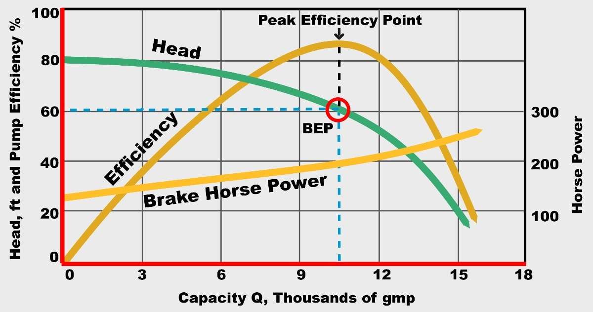
Pump performance curve are typically used for identifying or prediction of the changes in the process parameter (flow, differential Head, efficiency, power consumption etc.). Pump performance curve are the plot between different operating parameter. Pump performance curve can be obtained & designed from original Equipment Manufacturer (OEM). Identical performance curve for pump is indicated below.
Pump performance curve is required in case of selection of pump, troubleshooting & maintenance operation purpose. Below are provided two types of Pump performance curve format.
Pump Performance Curve
Cases against Pump performance curve plotted data is provided:
- Rated Case/Minimum Case/ Maximum Case: In this case flow rate considered is actual basis throughout the Process.
- Minimum Case: In this case flow rate considered is minimum (due to disturbance in process or future requirements minimum flow is in operation) for reference & necessary action against the plotted curve.
- Maximum Case: Maximum flow rate is considered for the Max diameter for Impeller.
Typically pump performance plot is indicated with operating parameter which directly dependent on each other are described below briefly:
1. Differential Head:
This point is indicated on Y Axis of Plot curve, differential head is simply difference between suction & Discharge side of Pump, however head is the measure of pressure, velocity or height of flowing liquid above the datum (reference point) from which all measurement is measured. Differential head can be Calculated from the below equation
∆P= Density of fluid * Acceleration due gravity * ∆H
∆H: (Difference in Height b/w two side of pump, i.e. discharge – suction side)
∆P: (Difference in Pressure b/w two side of pump, i.e. discharge – suction side)
Differential head is the parameter inversely proportional to the operating flow or capacity of pump (i.e. Differential head is reduced with increase in capacity or flow of the pump & vice versa.) Differential head is measured in meter (m).
2. Flow or Capacity:
It is the mass or volumetric flow rate which is available at the suction side or source of the pump. Unit measurement of Flow rate m3/h. Flow rate through pump is inversely proportional to the term differential Head. Flow rate is represent on the X-axis of the Curve.
3. Pump Efficiency:
Pump efficiency is defined as the parameter that directly upon the flow region in which pump is operating (i.e. flow at which pump gives the efficiency throughout the pumping operation). Pump efficiency is denoted as (n) and always expressed in percentage.
Within this curve there is a Point called as BEP (Best efficiency point) or Maximum efficiency point which is provided by the pump design through manufacturer, it is flow region in which pump produces the highest efficiency indicated with dotted line in the indicated diagram, as the flow rate move past (increase or decrease) this point the efficiency gets reduced accordingly as per the curve.
Let’s understand with an example a motorcycle operates with an average mileage of 35 Km at different or variable speed, but at certain speed motorcycle gives the highest mileage this is known as the efficiency.
4. NPSHR:
NPSH is Net positive suction head required which is also plotted on the Y Axis of the curve which is against the term volumetric flow rate; NPSHR is in direction proportion with volumetric flow rate. NPSHR should be always greater than the NPSHA (Net positive suction head available) Indicated NPSHR is inclusive of additional margin. NPSHR unit of measurement is in meters (m).
5. Power Consumption:
Power is plotted on the Y axis as well, power consumption increases with flow rate. It is expressed in BHP (Brake horse power).
Example: Fan consume less power when it is operating at low speed, if the RPM of fan increases so does the change in fan power consumption.
6. Shut off Head:
Shut off head is condition in which pump uses operating fluid load with zero head (fails to deliver the fluid at the designated height). Shut off head is indicated on pump curve at Y – Axis.
Example: During Plant watering process kettle is used, if we keep the valve knob in closed position then water is not reaching to plant spots (i.e. with fluid loading not delivering upto the plants).
7. Impeller Size:
- Generally in pump curve impeller diameter is indicated as minimum / rated / maximum against the Minimum / Maximum operating flow rate through the Pump. Impeller dimension decides the flow that pump can produce, impeller size & speed responsible for flow correlation. Affinity law stated that flow is directly proportional to the Impeller diameter & Speed.
Cases against impeller diameter provided: Rated Case/Minimum Case/ Maximum Case
Reference:- enggcyclopedia